
Part 1 – Air India 171 Crash: NO-GO Fault & Electric Arc


Air India crash: How AI 171 had NO-GO faults and still flew; leading to electrical cascade, systems failure
There is exclusive evidence that Air India 171 reported multiple NO-GO faults 15 minutes before takeoff and was still allowed to fly. Faults that likely resulted in an electric arc on the plane; as a high voltage inverter reached its thermal and dielectric limit, frying the emergency beacon, tail blackbox and knocking out the flight computers and avionics rack – a situation that ultimately could’ve led to engine computer FADEC getting corrupted data and cutting off fuel mid-air.
AI 171 was one of the shortest flights in aviation history. 32 seconds in total. From takeoff to crash.
A deadly tragedy that claimed the lives of 260. While everyone is familiar with the names of the pilots – Capt Sumeet Sabharwal and First Officer Cliver Kunders. On duty that afternoon of June 12, 2025, were also Air India 171 crew members like Shradha Dhavan, Aparna Mahadik, Saineeta Chakravarty, Nganthoi Sharma Kongbrailatpam, Deepak Pathak, Maithili Patil, Irfan Shaikh, Lamnunthem Singson, Roshni Rajendra Songhare and Manisha Thapa. Their names — representative of the ethnic diversity and cultural richness of India; just as much as the passenger list represented the broader global connect on that fateful day.
All of them boarded the flight, unaware that AI 171’s systems had likely begun unraveling. Months, days earlier. Deep beneath their feet; inside the aircraft’s labyrinth of wires and power buses.
The first domino: a failing core network
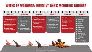
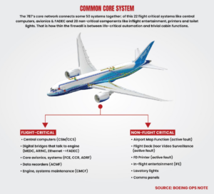
On June 9, 2025, maintenance staff logged that the plane’s core network was degrading, as per the Aircraft Accident Investigation Bureau (AAIB) preliminary report. But because Boeing in its operations notes to airlines minimised the damage an inoperative core network could do; maintenance marked the core network as medium-risk (can be fixed in 10 days). And this core network connected about 22 flight critical systems, including FADEC; apart from 28 other more mundane functionalities like the plane’s air conditioning. And later in this article, we’ll show how this was the more important fault and how it connects to all the other failures that followed.
But prior to core network degradation, the plane was already reporting cabin and cargo related faults in the weeks prior to the crash, as per the AAIB report. Engineers say this points to an intermittent electrical integrity fault affecting the common core cabinets and network interfaces — i.e., the shared platform that hosts cabin and cargo functions and flight critical systems. Now this could be because of electrical fault in the power conditioning module (PCM) — essentially the core cabinet’s internal power supply — which provides regulated electrical power to the aircraft’s network hardware, including the the data traffic router or ARINC 664 Cabinet Switch (ACS) and the the copper-to-fibre signal converter Fibre Optic Translator (FOX).
And it’s first victim was the common data network (CDN) or core network on June 9 (marked “medium-risk” or CAT C MEL), followed by a fire inerter, a stabilizer motor trim unit and then all three of the plane’s flight control modules by crash day.
Now let’s take a closer look at the second domino in the chain of failures. On June 10, the plane’s fire inerter or nitrogen generation system (NGS) — which prevents fires in the fuel tanks by depleting oxygen and replacing it with nitrogen — faulted. It was marked as “high risk” (CAT A MEL) and was likely physically inhibited by maintenance.
(Credit: Federal published content)
In technical terms, the AAIB report notes that the core network got marked a CAT C MEL or “medium-risk,” while the fire inerter got a CAT A MEL or “high-risk.” MELs or minimum equipment lists are the faults with which a plane is allowed to fly, provided it fixes these issues within a specified number of days. And on the day of the crash, Air India had 7 more days to fix the core network issue (till June 19, 2025) and 8 more days to fix the fire inerter issue, as per the AAIB report.
But the issues kept piling up and then there was a third domino. On June 12, the day of the crash, the stabilizer motor unit and sensors faulted and had to be replaced on the previous morning flight (AI 423 Delhi to Ahmedabad), as per reports.
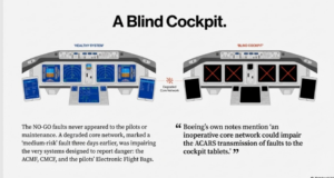
D-Day: A jet in fault mode, a cockpit left blind
The plane’s condition kept deteriorating.
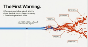
On June 12, 2025, the day of the crash, 15 minutes before takeoff; at 1.23 PM IST, the aircraft’s ACARS logs started streaming… “BPCU OPS…FCM OPS…CMCF OPS…GPM OPS….HYDIF OPS….”
“OPS” in Boeing maintenance parlance is “Operations” — shorthand for a detected operational fault. And AI 171 didn’t have one, but multiple operational faults, according to data shared by two independent sources. Malfunctions serious enough to disrupt electrical power stability and data flow across the length and breadth of the 120-tonne carbon-fiber leviathan.
(Graphic by Capt Amit Singh)
A NO-GO plane that still flew
And not just operational faults, but NO-GO items as well. Regulations don’t permit planes to fly with faults as severe as these. So how did AI 171 still fly with no one being the wiser?
Rewind to three days earlier, on June 9, when the jet’s core network was marked an active fault. This core network once it starts degrading can also impact the function of the systems that report faults — the Aircraft Condition Monitoring Function (ACMF), the Central Maintenance Computing Function (CMCF), and even the pilots’ Electronic Flight Bags (EFBs).
Boeing’s internal note itself mentions this possibility, saying, “an inoperative core network could impair the ACARS transmission of faults to the cockpit tablets or EFBs.”
By June 12, the day of the crash, the timing of the failures had turned vicious. The NO-GO faults were occurring at the exact moment the systems responsible for reporting NO-GO faults were themselves failing. The fault-reporting chain went dark.
So when maintenance signed off on the jet at 12:10 PM IST and when the pilots performed their checks at 1:23 PM IST — the critical faults or NO-GO items simply never appeared.
So maintenance didn’t know. Pilots didn’t know. But Boeing would’ve known. And so would Air India.
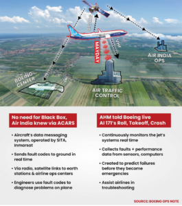
The ACARS ring that bound them all: Boeing, Air India, SITA, Inmarsat
As the plane kept sending out warnings — upstream, Boeing and Air India were seeing everything. Like Sauron’s unblinking eye, they were receiving a ring of real-time data from the aircraft’s digital datalink, ACARS.
That ring formed a tight closed loop: carried by Air India’s sub-contractor SITA, relayed over satellite provider Inmarsat, and delivered to Air India’s operations centre in Gurugram and Boeing’s data monitoring hub in Belleville, Illinois, US.
At 1:23 PM IST, that ring flashed three sets of NO-GO warnings. ACARS told everyone in the loop that AI 171’s left and right bus power control units (BPCUs), the computers that act as traffic controllers for electrical power, had entered fault mode, unable to keep the left and right 115-volt AC buses in sync. Meaning the airplane’s two main power highways were falling out of phase, a condition that can cause surges, flickers, or even short-circuits across systems.
The domino effect: Flight computers, processors fall one by one
Next, all three flight control modules (FCMs) left, right and centre began reporting operational errors. These are the units at the heart of the 787’s fly-by-wire system. They take instructions from the flight computers and translate pilot inputs into precise movements of the stabilizer, ailerons, and spoilers.
And it doesn’t stop there. Two general processor modules (GPMs) also faulted. These were the 787’s backstage processors; running key software, performing calculations that feed flight management and crew alerting and the nerve-centre for fault detection and reporting.
Taken together — the out-of-phase power buses, failing flight control modules, and glitching GPMs — AI 171 wasn’t dealing with a single fault but a system-wide degradation. As pilot Rajneesh S puts it, “Aviation outcomes emerge from complex, tightly coupled systems… failures rarely stem from a single decision or individual lapse.”
And yet, the plane was cleared for takeoff at 1:25:15 PM IST.
The plane’s pilots — Capt Sumeet Sabharwal and First Officer Clive Kunders, unaware of what was happening inside, guided the plane to the runway. Started roll and lifted-off at 1:38:39 PM IST.
A surge, an arc, a cascade of collapse
Now, takeoff is always the most electrically demanding phase of flight — all four power channels, bus control units, and hydraulic pumps draw maximum load as the plane transitions from ground to airborne mode.
For AI 171, that surge became catastrophic. And core network degradation could’ve caused an electric arc. Now we’ll show you how AI 171’s systems could’ve arced by tracing the failure chain back to what happened on the previous flight of VT-ANB.
“Gremlins” in VT-ANB; blank screens to blackout
A few hours before the crash, passenger Akash Vatsa — seated aboard the same aircraft VT-ANB on its previous flight (AI 423) from Delhi to Ahmedabad— recorded a short video complaining that the air-conditioning and in-flight entertainment weren’t working, and that even the crew call buttons were dead. Post-crash when he posted the video, viewers mocked him — calling him a fussy traveller who didn’t understand aircraft systems. But Akash was perhaps unknowingly documenting the first public evidence of a deep electrical failure spreading through VT-ANB’s core.
Trolled for it; but 787’s Architecture vindicated Akash
“I was badly trolled, people said I was just doing it to gain publicity; linking the inflight entertainment with air conditioning makes no sense and neither it has anything to do with the crash…I was told a non-working AC and inflight entertainment is very common in Air India,” Akash Vatsa told this reporter.
But turns out Akash was right. On the 787, the in-flight entertainment, cabin climate control, and crew communication panels are not isolated luxuries; they share both power and data on the aircraft’s core network. The same core network that connects 22 flight critical systems including the pathways to engine computer FADEC.
So in a scenario that resembles Lewis Caroll’s Alice in Wonderland, engineers say Boeing has created its own electrical hard-to-believe architecture, where the air conditioning, a non-flight critical system, sits ensconced on a network with other flight critical systems.
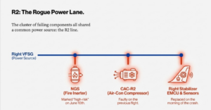
And one of the cabin air conditioning’s compressors was sharing the same power source — a high voltage inverter, managed by a common motor system controller (CMSC R2) on the R2 line — as the fire inerter (NGS), marked “high-risk” two days earlier. The same R2 line which on the same flight also saw its right horizontal stabilizer electric motor control unit (EMCU) and stabilizer sensors fail during the descent phase, before landing.
R2: The Rogue Power Lane
So when the cabin air conditioning’s cabin air compressor (CAC) is in a bad power domain experiencing power surges and voltage spikes — it can result in fluctuating air conditioning as Akash and other passengers on Flight 423 (VT-ANB) experienced.
Below is the power path mapping from the right engine’s variable frequency starter generator (VFSG) to the high-voltage drive used by the fire inerter (NGS) and the right compressor (CAC); and to the power conversion system (PCS) to the right stabilizer motor (EMCU) and sensors.
Power paths:
R2 235 V AC main bus → ATRU R2 → ±270 V HVDC → CMSC R2 → NGS/ CAC-R2 / Hyd L EMP
L2/R2 235 V AC main bus → PCS (115 V/±130 V/28 V) → right stabilizer EMCU (115 V/±130 V) → right stabilizer sensors (28 V)
This shows the cluster of failing components — be it the fire inerter (NGS), stabilizer motor (EMCU) or the air-conditioning compressor (CAC) — were all on the R2 line.
Line 26: Legacy of the “Terrible Teens”

The problems faced by Air India’s Dreamliner AT-VNB have their origin in the ‘Terrible Teens,’ say experts. In aviation parlance, the “Terrible Teens” refers to a cluster of early-build 787s that came off the assembly line with serious manufacturing defects, requiring heavy rework; becoming notorious inside the industry for persistent quality problems.
“You see VT ANB (AI 171) was only the twenty sixth 787 built (line #26) , and back then the 787 factory in Everett, Washington was known to be having a lot of manufacturing quality issues,” Ed Pierson told the reporter.
He said one area of particular concern was the aircraft’s electrical wiring interconnect system (EWIS). “Over the years, we’ve seen some very dangerous EWIS practices across multiple Boeing programs — not just the 737, but the 787 as well. Fatigued employees, skipped installation plans, poor electrical bonding and grounding, improperly installed wire bundles, unqualified staff performing electrical work, rushed functional systems testing, and the removal of long-standing quality inspections— all of this can create latent defects in a variety of aircraft systems that can be extremely difficult to troubleshoot,” said Pierson. He adds, “These flaws often produce those frustrating ‘No Fault Found’ or ‘Could Not Duplicate’ maintenance reports. In the military, we used to call them gremlins.”
Was Fire inerter a victim to power transients?
And if we rewind a little here, we can see how the first gremlin may have been the fire inerter. Remember how two days before the crash on June 10, maintenance engineers had marked the fire inerter (NGS) a high-risk fault?
Well this fire inerter (NGS) is designed to prevent explosions by flooding the 787’s fuel tanks with nitrogen-enriched air and depleting its flammable vapour i.e. “live” oxygen. To feed that flow, the NGS uses a compressor and a high-voltage inverter, controlled by a common motor system controller (CMSC R2). And this high-voltage power line (CMSC R2 ±270 V) also feeds a cabin air compressor (CAC) and hydraulic electric motor pump (L) in the aft power distribution bay. The same compressor (CAC) whose faults were visible to the passengers above when the air-conditioning fluctuated on the previous flight (AI 423).
Where cooling failure becomes combustion risk
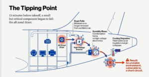
Now comes the most inconspicuous but dark horse fault of all on the crash flight. In the tail section there is an aft zonal dryer, a small unit that removes moisture from the ventilation air around the fire inerter (NGS), compressor and its cooling ducts.
On AI 171, this started showing abnormal readings at 1.23 PM IST, 15 minutes before takeoff, as per data from two independent sources.
This would lead to moisture building in the aft bay; a sharp rise in humidity as the dryer isn’t removing water vapor. Condensation risk increases as droplets can form on wiring, high voltage inverters, raising the risk of short circuits or even an arc. And the cooling efficiency also drops as the moisture load would make the environmental control system (ECS) work harder and reduce heat removal margin from electronics.
Water turns fire: How aft-bay moisture caused electrical failure
Given what Ed Pierson and other whistleblowers have said about Boeing’s practises and improper bonding of the electric wiring interconnected system (EWIS) — a latent EWIS defect could also play in.
So 15 minutes before takeoff and 2 minutes before taxi clearance, it’s possible the AI 171’s aft high voltage system was in an unstable state. With cooling faltering, heat building up, moisture settling in and the twin power buses (BPCUs) slipping out of phase, the airplane’s systems were likely reaching their tipping point.
Zonal dryer turns tail into heat zone: The first ripple in AI 171’s core
And then they seemed to have tipped over. As per data from the sources the “aft zonal dryer” anomaly seen at 1:23 PM IST likely escalated into a full-blown failure after takeoff at 13:38:39 IST.
Flight logs accessed show an ACARS message (167280002) shows that there was a failure on the aft zonal dryer’s control feedback path in the integrated cooling system (ICS) that connects to the aircraft’s core data network. Or in other words the moisture-removal or dehumidification loop in the tail section likely failed.
High voltage inverter drives turns metal-melting arc source
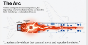
When the aft zonal dryer fails, humidity rises and the insulation margin inside the high-voltage inverter, controlled by CMSC R2, drops sharply. If the BPCUs are also faulting, power quality can swing violently and protection may not isolate the inverter when it should. At the same time, a degraded core network can delay or corrupt trip commands, keeping the inverter energised even as its insulation environment is collapsing. And loads such as cabin air compressors for the air conditioning would likely put more stress on the inverter precisely as the insulation environment was most vulnerable.
Under these stacked conditions, the high voltage inverter would possibly become increasingly vulnerable. As the heat builds up it is likely the inverter reached its thermal and dielectric threshold limits — meaning its cooling and insulation could no longer contain the voltage.
“When that happens the inverter will discharge through nearby wiring harnesses a sustained electrical arc, a plasma-level short that can melt metal and vaporize insulation,” said a flight engineer, who did not want to be named.
The surge that reached the Dreamliner’s nerve center
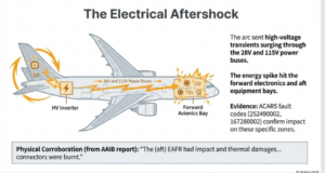
So if a high voltage inverter arced; then this burst of energy would’ve sent transients — sharp voltage spikes — surging back through the airplane’s 28-volt and 115-volt power buses, rippling through the core network, the data-power spine that links almost every system on the 787.
And it looks like it did — because ACARS fault codes (252490002, 167280002) indicate that this arc likely hit the forward electronics and electrical bay. And they were probably hit harder than they normally would have because of the existing faults before takeoff.
When two power lines fail, two others carry the plane — until they don’t
At 1.23 PM IST, 15 minutes before takeoff, when the system began throwing up processor (GPM), fault monitoring system (CMCF), power controller (BPCU faults) this would have impacted the power routing of flight critical systems.
The plane has two engine generators (left and right VFSGs) supplying power to four lines — L1, L2, R1 and R2. Given the nature of the faults, the system would have first decided to route flight critical components away from L1 as this line had multiple faults (GPM Left 1 + CMCF Left + BPCU Left) and would have been identified as an unclean source of energy. The next line that would’ve been marked as suspect would have been R1 as this too had faults (GPM Right 4 + BPCU Right). Leaving L2 and R2 as the lines that were probably being used most by the flight critical components on the plane. If L2 or R2 were the components’ secondary electrical path.
The arc that hit the heart: the R2 power-line arc
But these two lines L2 and R2 were also seeing components faulting. At 1.23 PM, 15 minutes before takeoff, the right hydraulic electric motor‑driven pump on the L2 line was faulting (HYDIF RIGHT OPS). And as we discussed earlier the R2 line had already seen the fire-inerter (NGS), stabilizer motor (EMCU) and air conditioning compressor (CAC) failing.
So given more than normal components might be mapped on to the L2 and R2 lines – an arc on the R2 line could’ve had far more impact than normal as it hit the forward and aft avionics bay.
Once forward and tail avionics are hit they can begin spitting corrupted data and degraded voltage states. And those kinds of faults can bleed directly into FADEC logic. If FADEC sees invalid or contradictory control signals — it can try to “protect the engine” by limiting thrust during takeoff roll. And more dangerously — if this happens once airborne — FADEC could decide to shut the engines.
When power source for cooling systems starts the fire
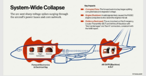
The irony could not be more brutal. If the above interpretation is true the power sources for systems designed for cooling and to prevent fires — appears to have ignited the airplane’s electrical core instead. The high voltage inverter of the fire inerter and airconditioning likely arced to structure, burning through the aft equipment frame, cooking the wiring of the emergency distress beacon (ACARS code 252490002), crippling the auxiliary power unit (APU), charring the tail blackbox (aft EAFR), cutting the anti-collision strobe lights and starting a blackout that killed half the aircraft’s avionics and its lines to the engines.
The scenario of the plane’s ELT and EAFR getting knocked out by an electric arc is consistent with the AAIB report, which says, “the Emergency Locator Transmitter (ELT) was not activated during this event…..the (aft) EAFR had impact and thermal damages to the housing. The wires were protruding from the housing and the connectors were burnt.”
Boeing Papers Admit: Single Fault Can Trigger 787 Cascade
This possibility of an arc on the R2 line cascading across multiple systems is admitted by Boeing in an internal document, where it states, “The loss of a single component within the common core system (CCS) can affect multiple systems.” And on AI 171, the component failing – if it can be called that – was the core network. The host of the central computers, CCS, flight control computers and the command arm of the power controllers or BPCUs.
Boeing itself states that the 787’s architecture “differs from the traditional aircraft system, where each individual system requires its own dedicated communications route…the 787 architecture reduces the amount of wiring, hardware and overall weight of the airplane…and in this architecture, individual component failures can impact multiple systems.
Neither Boeing, Air India, DGCA India, AAIB, or other regulatory agencies like EASA have responded to request for comment.
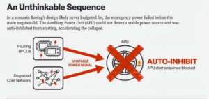
What Boeing didn’t design for: emergency power failing before engines
And then comes an event that could star in Ripley’s “Believe it or Not” as this plane seems to have had its emergency power fail before the engines did. An ACARS fault code (163840003) could indicate the APU’s control unit was also hit in the power transient.
But even if one didn’t go by the fault code but just by logic and Boeing literature, then again the emergency power or auxiliary power unit (APU) will not function until it can clearly determine a stable high-voltage source. And on AI 171, the APU likely didn’t have that.
The power gatekeeping BPCUs had started faulting and the core network was degraded — meaning commands to isolate a failing unit would get delayed or corrupted. So in this deck of cards, when one of the high voltage inverters arcs, with no clean high-voltage source, the 787 can auto-inhibit APU start. Because Boeing’s design philosophy was that loading a heavy consumer like the APU starter motor onto an unverified rail risks accelerating the collapse. What it wasn’t budgeting for was an electric failure that possibly first crippled the emergency power, before it triggered dual engine failure, say engineers.
The APU That ‘Looked Fine’
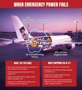
But going by the AAIB report, you wouldn’t think anything was amiss with the APU. As AAIB report states, “ÄPU was recovered intact…APU inlet door began opening at 08:08:54 UTC.”
Engineers say APU inlet door opening was probably a result of manual action by Captain Sumeet; and not system-driven as the 787 is unlikely to auto-start in the middle of a surge on the high-voltage drive line.
Faults treated in isolation hid electrical failure behind 787 crash
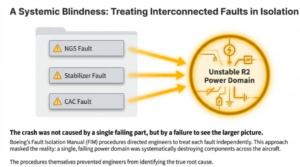
So going back in time, the fire inerter (NGS) being identified as an active fault on June 10 seems to have been the alarm siren for a deeper electrical problem on the plane. In hindsight the engineers say the crash itself may have never had happened had the NGS and stabilizer motor problem not been seen in isolation as Boeing’s fault isolation manual (FIM) asked engineers to do.
If Boeing and the airline had given engineers more authority, leeway and time when it came to dealing with faults, engineers say they are certain that the root cause would have been identified. That it was likely a bad power domain that had impacted the fire inerter, stabilizer motor unit and finally the high voltage inverter — triggering an arc that likely hit the forward avionics rack and inputs to engine computer FADEC — possibly resulting in engine shutdown and ultimately the plane crash.
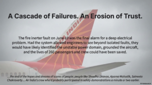
And the end of the hopes and dreams of scores of people; people like Shradha Dhavan, Aparna Mahadik, Saineeta Chakravarty, Nganthoi Sharma Kongbrailatpam, Deepak Pathak, Maithili Patil, Irfan Shaikh, Lamnunthem Singson, Roshni Rajendra Songhare and Manisha Thapa — Air India’s crew who’d probably participated in safety demonstrations a minute or two earlier.
(Disclaimer: The AAIB has not yet released its final report on the AI-171 crash. All the technical scenarios presented here are based on preliminary information, evidence submitted in India’s Parliament and Supreme Court and remain hypotheses. Also the ACARS codes mentioned in the story are not a direct map to maintenance faults as listed in Boeing’s Fault Isolation Manual; as maintenance faults are 7-8 digit strings. The 9-digit ACARS string is only partially recognisable to engineers as its proprietary code of Boeing. For this story on conditions of anonymity we have spoken to pilots and flight engineers in India, Europe and US; and for details on actuators, sensors, structural engineering and logic paths to IT, mechanical, electrical and electronic engineers from India, working for firms that are Boeing sub contractors.)